Causes and Solutions for Excessive Motor Vibration
Motor vibration problems can affect equipment performance and service life. Since all stepper motors have an inherent resonant frequency, it is important to implement targeted measures early in the equipment design phase to eliminate potential vibration hazards. One common cause of excessive vibration is the mechanical structure of stepper motors, which can cause slight position deviations in the rotor during operation. When the rotor passes its target position due to inertia, periodic oscillations may occur. If the frequency of these oscillation matches the motor's natural frequency, resonance will occur, often accompanied by noise. If the resonance energy exceeds the magnetic holding force between the stator and the rotor, the motor may lose steps. The following section provides a detailed explanation of how to address excessive motor vibration. 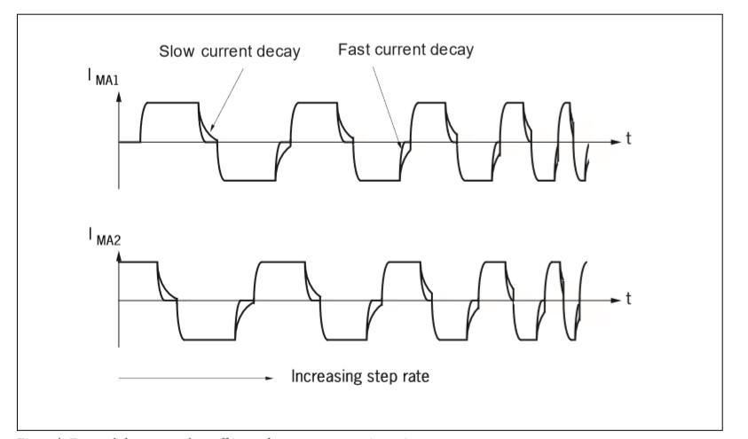 Figure 1. Current Signal from the motor drive
 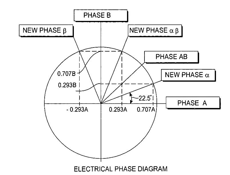 Figure 2. Phase diagram of the R-winding Single-phase conduction and dual-phase conduction modes exhibit different stable period characteristics due to the variations in current distribution. The inconsistency in their stable times can easily trigger resonance. The R-type winding motor adopts a special pole slot structure, with each magnetic pole equipped with two sets of coils having different turn counts. The coil group employs an alternating-direction series winding method (the end of the first set of coils is connected to the start of the second set), and the 22.5° electrical phase offset design is implemented to effectively suppress vibration noise. The winding topology introduce an innovative 1/8 microstepping phase sequence (22.5°, 67.5°, 112.5°, 157.5°, 202.5°, 247.5°, 292.5°, 337.5°) to eliminate single-phase excitation conditions. The drive system consistently energizes the two-phase winding and ensures the stability of each step cycle's time through current balancing, thereby significantly reducing the risk of resonance.
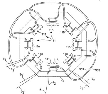
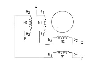 Figure 3. Winding setup of the R-winding The use of T-type winding connection is an effective technical solution for suppressing resonance. This topology maintains a two-phase continuous energization mode, and its vibration suppression mechanism is equivalent to that of the R-type winding - the two-phase excitation mode effectively reduces the likelihood of system resonance. The electrical characteristics of this connection method are such that the winding inductance lies between the fully series and fully parallel configurations. This compromise design enables the T-type topology to deliver better torque output under low-speed conditions than the parallel connection, while maintaining stronger torque retention during high-speed operation compared to this series mode.
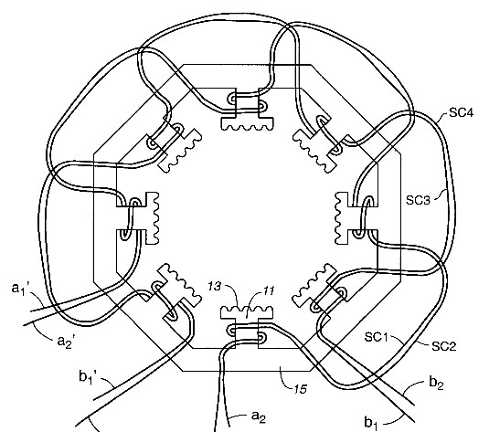
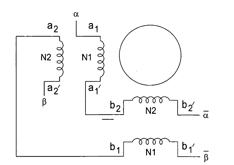 Figure 4. Winding setup of the T-connection Generally, increasing the number of motor phases can effectively suppress resonance. The more phases a motor has, the smaller the step angle, which is similar to the principle of microstepping drive technology. As the number of phases increases, the excitation energy required to rotate the rotor decreases, effectively eliminating resonance issues. For example, consider a two-phase motor and a five-phase motor: the two-phase motor uses an 8-pole structure (4 poles per phase), while the five-phase motor uses a 10-pole structure (2 poles per phase). In a five-phase motor, the rotor only needs to move 1/10 of the tooth pitch to align with the next phase magnetic pole, allowing one full rotation to achieve 500 step cycles (step angle 0.72°). The higher angular resolution reduces the excitation energy needed for each step, effectively controlling overshoot during rotor movement. When combined with microstepping drive technology, the five-phase motor can achieve even finer step resolution, significantly reducing operational vibration.
 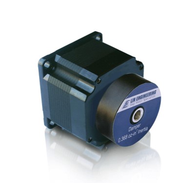 Figure 5. A common NEMA 23 mechanical damper Another mechanical vibration reduction method is to suppress vibration by adjusting the rotor inertia. Modifying the load inertia alters the system's resonant frequency characteristics. Engineers can optimize the rotor inertia by selecting different materials, adjusting geometric dimensions (such as increasing the rotor length), or employing a specific laminate structure (see Figure 4). These adjustments can shift the system resonant frequency, effectively reducing the vibration amplitude.
 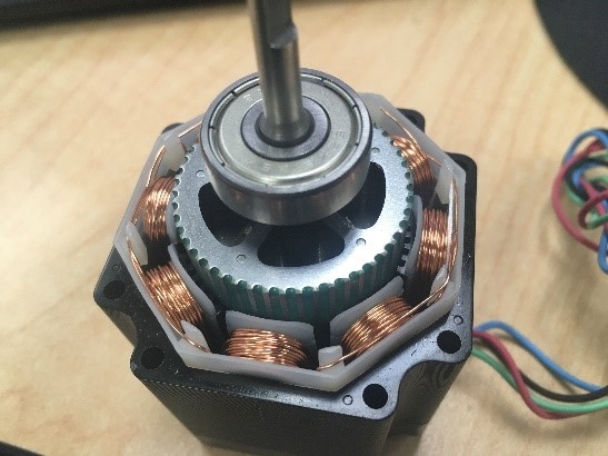 Figure 6. Low inertia rotor design The torque stiffness parameter can be effectively controlled by adjusting the air gap size between the rotor and stator slots. As specified in the technical guidelines, this adjustment alters the motor's output torque characteristics, shifting the system operating point deviate from the resonance region, thereby avoiding vibration issues. When the motor drives the load, the load inertia significantly increases the system's overall rotational inertia (acting similarly to a mechanical damper), which results in a notable reduction in motor vibration amplitude. Understanding the working principle of stepper motors is crucial for selecting the right product for your application. MOONS' offers a wide range of signature products that can meet your needs. If you have special requirements, feel free to contact us for direct customization.
Electrical vibration reduction method
This section primarily focuses on how to prevent resonance in stepper motors. It is important to note that the motor's physical characteristics, electrical parameters, and operating conditions can all be optimized and adjusted. It is recommended to carefully assess the applicability of each solution based on specific working conditions. For special application, it is advisable to consult with professional technicians. 1. Adjust the operating frequency: When resonance occurs in a specific speed range, the most straightforward solution is to adjust the operating frequency to avoid the inherent resonance frequency. Although this method may be limited in certain application scenarios, it can not only eliminate resonance but also enhance system efficiency under feasible conditions. 2. Control microstepping: Microstepping technology suppresses vibration by increasing the subdivision of the step angle. In traditional full-step operation, the abrupt changes in magnetic flux caused by the coil's switching can easily lead to rotor overshoot. Microstepping control adjusts the coil excitation energy in a gradual manner, enabling a continuous and smooth transition of the stator magnetic field, which effectively reduces the rate of change of magnetic flux. This technology can reduce vibration noise and improve motion resolution. 3. Optimize current control: In low-speed application such as medical equipment and robot joints, appropriately reducing the drive current can enhance operational stability. While decreasing the current magnitude will lower the output torque and torque stiffness coefficient (dτ/dθ), it effectively controls the rotor's kinetic energy. During implementation, it is crucial to ensure that a sufficient torque margin is maintained to prevent secondary control issues. 4. Inductance compensation technology: During motor operation, the AC induced current generated by resonance can interference with the driving DC current, creating a superimposed disturbance. By increasing the winding inductance, the system's resonant characteristics can be adjusted to achieve a shift in the resonance frequency or suppress its amplitude. 5. Current decay optimization: The fast current decay mechanism can effectively improve vibration characteristics. During the commutation process, the instantaneous decay when the current direction is switched helps reduce residual current interference and prevents torque pulsation caused by the superposition of dual current signals. Comparative experiments demonstrate that using the fast decay mode can significantly reduce the operating vibration (see Figure 1 for details). Figure 1. Current Signal from the motor drive
 Implementing R Windings with Two Phases On
In a hybrid stepper motor, the stator adopts a two-phase winding structure, with the coil spatial distribution differing by 90° electrical angle. The phase switching in a traditional stepper winding system increases by 45° step angle, with the specific sequence being: 0°, 45°, 90°, 135°, 180°, 225°, 270°, 315°. When the phase difference is 45°, both the A and B phase windings are energized simultaneously. However, when the phase difference is adjusted to 90°, only the single-phase winding is in the excitation state. Figure 2. Phase diagram of the R-winding Single-phase conduction and dual-phase conduction modes exhibit different stable period characteristics due to the variations in current distribution. The inconsistency in their stable times can easily trigger resonance. The R-type winding motor adopts a special pole slot structure, with each magnetic pole equipped with two sets of coils having different turn counts. The coil group employs an alternating-direction series winding method (the end of the first set of coils is connected to the start of the second set), and the 22.5° electrical phase offset design is implemented to effectively suppress vibration noise. The winding topology introduce an innovative 1/8 microstepping phase sequence (22.5°, 67.5°, 112.5°, 157.5°, 202.5°, 247.5°, 292.5°, 337.5°) to eliminate single-phase excitation conditions. The drive system consistently energizes the two-phase winding and ensures the stability of each step cycle's time through current balancing, thereby significantly reducing the risk of resonance.


Mechanical vibration reduction method
Vibration can be effectively suppressed by optimizing the motor's mechanical structure. A common method is to Install a damper on the motor shaft end. The damper absorbs vibration energy while increasing the system's moment of inertia, thus forming a stable damping mechanism. Additionally, using a flange mount can enhance the structure's ability to absorb vibrations. Figure 5. A common NEMA 23 mechanical damper Another mechanical vibration reduction method is to suppress vibration by adjusting the rotor inertia. Modifying the load inertia alters the system's resonant frequency characteristics. Engineers can optimize the rotor inertia by selecting different materials, adjusting geometric dimensions (such as increasing the rotor length), or employing a specific laminate structure (see Figure 4). These adjustments can shift the system resonant frequency, effectively reducing the vibration amplitude.
  Figure 6. Low inertia rotor design The torque stiffness parameter can be effectively controlled by adjusting the air gap size between the rotor and stator slots. As specified in the technical guidelines, this adjustment alters the motor's output torque characteristics, shifting the system operating point deviate from the resonance region, thereby avoiding vibration issues. When the motor drives the load, the load inertia significantly increases the system's overall rotational inertia (acting similarly to a mechanical damper), which results in a notable reduction in motor vibration amplitude. Understanding the working principle of stepper motors is crucial for selecting the right product for your application. MOONS' offers a wide range of signature products that can meet your needs. If you have special requirements, feel free to contact us for direct customization.