Skip to content Skip to navigation menu

The 5 Most Important Considerations for Motion Applications

Motion control applications require many considerations. As part of the design process for a reliable high-performance motion system, a number of questions need to be answered, such as what type of motor to use, what drive to use, how to get feedback from the system, and how to synchronize movements and get different parts of the system to communicate. The 5 Most Important Considerations for Motion Applications
Motor Technology

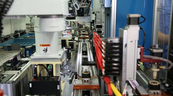
Choosing the right motor for any motion application is the first step in determining the application's success. Stepper motors, brushed or brushless servos, and synchronous or induction AC motors are among the most common types of motors. Specific motors are typically selected based on their torque and speed characteristics. Feedback is crucial for closed-loop control, and a variety of sensors are available, like encoders, resolvers, tachometers, etc. Position information is given by relative encoders, whereas absolute encoders hold the shaft's absolute position and are useful when the position is needed at startup.

Communications Bus

The Communication Bus is responsible for transmitting motion commands from the controller to the drive. The communication may be through analog signals, digital step and direction commands, or over deterministic communication buses. In choosing the communication bus, many factors are taken into account, the most significant one being the distance between the motion controller and the drive and the presence of ambient noise. For example,in a noisy environment, a communication bus like EtherCAT may be more feasible than analog signals. However, this selection is also highly dependent upon the compatibility between the motion controller and the drive being selected especially when they are being provided by different vendors.

Coordination

To determine whether multiple axes need to be coordinated or synchronized, it is important to evaluate the motion profile and application requirements. Synchronizing multiple axes of motion would require deciding on a motion vector, resolving it into components for different axes, and passing these commands synchronously to those axes. Alternatively, electronic gearing could be used to make one axis serve as a slave for another. In those cases, the slave trajectory can be calculated by scaling the master set-point. In addition to synchronizing motion with cameras or sensors, there can be other requirements. For example, a motion system for testing an HMI might require a pressure transducer as a source of feedback to apply just the right pressure through the probe. In an End-Of-Line inspection and testing, a camera may be responsible for commanding the motion system.

System Architectures

Once the hardware and synchronization requirements are determined, you can decide where the control code will run. There are two main ways to set up a motion control system, either to have most of the control code be within a single target or to separate the computation among multiple nodes. The first approach can be implemented by a central system such as a PC with motion control cards. Systems of this kind are easy to set up, but scalability in terms of PCI slots, etc., is a limitation. As an alternative, a supervisory system can generate the trajectories and provide them to a distributed smart drive that runs the lower level torque and velocity control loops. The only limitation in these kinds of systems is that the synchronization is limited to the communication bus. A daisy-chained network of smart EtherCAT drives can be a classic example of this kind of system.

Development Software

Some motion systems act on their own while others may require integration with other systems like vision. Some of the features required are modularity of the software which can allow you to change the drives (from different vendors) without much change in the code. Additionally, the software generates motion profiles that can be tested within a simulation environment. In most cases, this is accomplished by generating the trajectory and plotting it or sending it to a simulated drive or a model of the drive and motor. Finally, a model of the motor could be used to test most of the code and some tuning before moving to a physical one. In conjunction with the motion system, mechanical simulation software such as SolidWorks is usually used.