Field Oriented Control of Brushless Motors
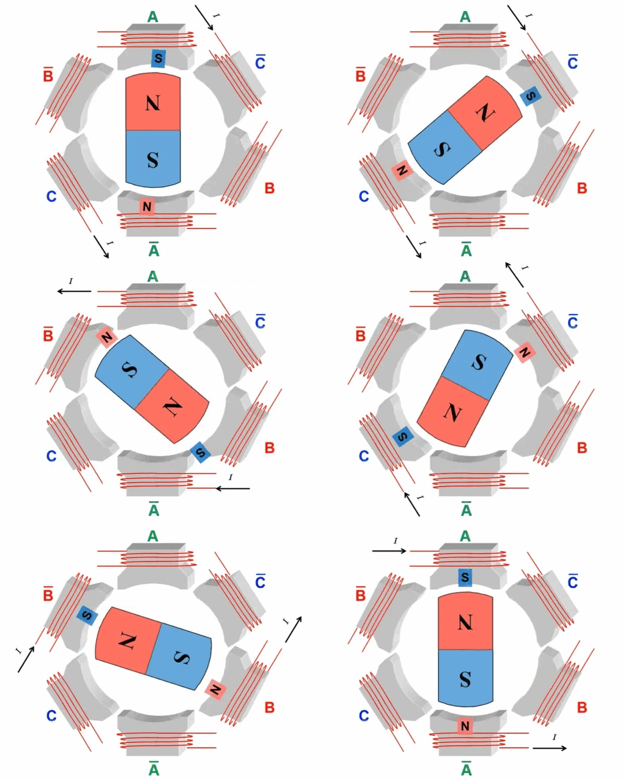
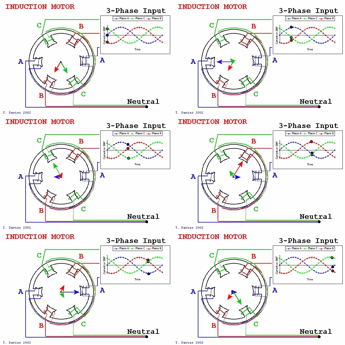
Field-Oriented Control (FOC), also known as vector control, is a sophisticated motor control strategy. This method involves managing the amplitude and frequency of the output voltage from an inverter to control a three-phase DC brushless motor. The essence of FOC lies in its use of coordinate transformations, which convert the motor's phase currents from a stationary three-phase coordinate system into a rotating coordinate system aligned with the rotor's magnetic pole axis. By manipulating the magnitude and direction of vectors within this rotating framework, FOC effectively regulates motor performance, achieving precise control over the motor's operations. 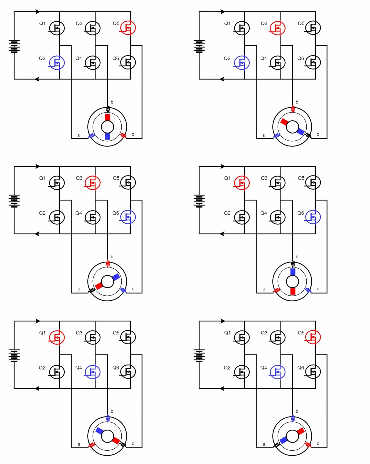 When Q1 and Q4 are activated, the current flows from phase A to phase B and then exits through the negative terminal. According to the right-hand screw rule, during this process, the A-phase coil of the stator generates an inward-facing N-pole magnetic field, while the B-phase coil produces an inward-facing S-pole magnetic field. This causes the stator coils to attract the rotor magnets, based on the principle that like poles repel and opposite poles attract, resulting in rotation. When Q5 and Q4 are subsequently turned on, the direction of the current changes, causing the C-phase coil of the stator to create an inward-facing N-pole magnetic field and the B-phase coil to maintain its inward-facing S-pole. Following the right-hand screw rule, this further rotates the rotor poles. By alternately switching different MOSFETs, the alternating movement of the motor poles is achieved, thereby driving the motor's rotation. The following figure shows the rotation process of the inner rotor brushless motor:
  The fundamental principle behind the rotational motion of this motor type lies in the precise control of the MOS' switching states. This precise manipulation allows for exact control over the motor's speed and direction. Owing to its specialized design and sophisticated control techniques, brushless motors are extensively adopted across various applications for their precise performance capabilities. The control of MOS switching patterns requires the assistance of a microcontroller program, which introduces the FOC (Field-Oriented Control) control algorithm. FOC control is a method that abstracts and simplifies the motor's motion model. Based on the motor's mathematical model, this approach determines the optimal switching and on-off states of the MOS by measuring parameters like current, speed, and position, thus enabling precise motor control. FOC control standardizes the switching and on-off processes of each MOS, ensuring the motor operates stably and efficiently. Under the assumptions: 1. The stator winding is a 60° phase-band full-pitch winding; 2. The sawtooth effect and magnetic circuit saturation are not considered; 3. The influence of hysteresis, eddy current, skin effect, and temperature on the parameters are ignored; 4. The three-phase stator winding is symmetrical, Ra=Rb=Rc,La=Lь=Lc,Mab=Mbc=Mca The following kinematic equations of the brushless DC motor are:
  In the formula, TL is the load torque, J is the motor moment of inertia, and B is the damping coefficient.
 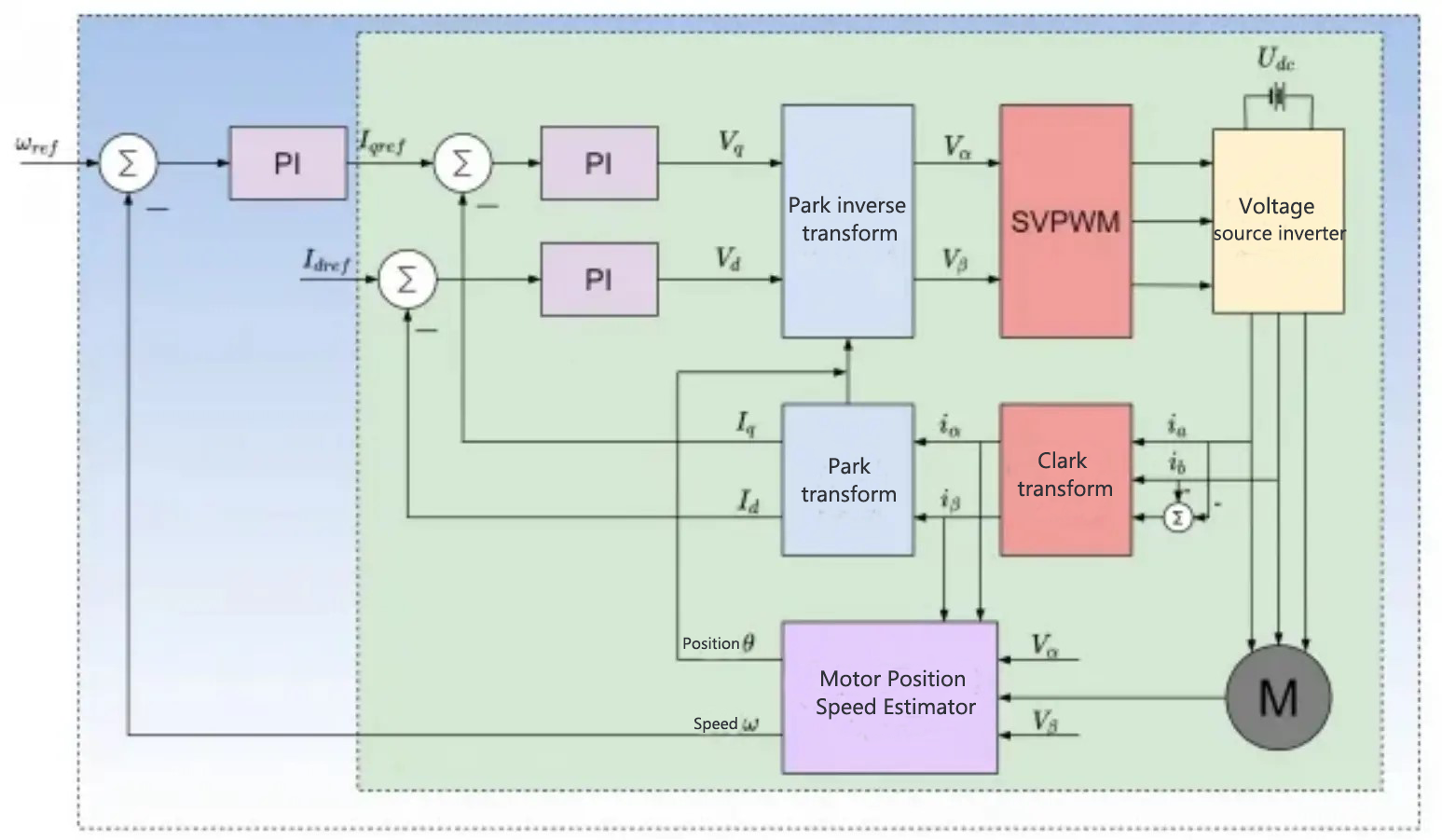 1.By measuring the three-phase stator currents ia, ib, and ic during the operation of the motor, these currents are transformed into two-phase currents iα and iβ through the Clarke transform. These two-phase currents are mutually orthogonal and represent time-varying current signals. 2. The two-phase currents iα and iβ are transformed into the currents Iq and Id within the rotating coordinate system using the Park transform. When the motor achieves a stable state, Iq and Id become constants. At this point, the rotor position employed is the angle calculated from the previous iteration. 3. The reference values for Id and Iq determine the flux of the motor rotor and the motor's torque output, respectively. The discrepancies between their actual values and reference values generate errors, which are then used as inputs for the current loop PI controller. This PI controller processes these inputs to calculate and output the voltages Vq and Vd, which form the voltage vector to be applied to the motor windings. 4. The motor rotor position estimator can calculate the new rotor angle and motor speed. This new rotor angle informs the FOC algorithm of the location for the next voltage vector. Additionally, the determined motor speed serves as crucial data support for various sub-function modules, including motor state transitions, loop switching, and stall protection. 5. Using the new motor angle, Vq and Vd are inverted to the two-phase stationary coordinate system through Park inverse transformation. This calculation will generate the next orthogonal voltage value Vα and Vβ The SVPWM algorithm is then used to determine in which sector the synthesized voltage vector is located, and calculates the conduction times for the switch tubes in each of the three-phase bridge arms. Ultimately, the necessary three-phase voltage for the motor is delivered through the three-phase inverter drive module.
 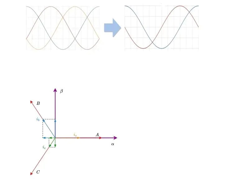 In the three-phase stator coordinate system, the phase difference between the three-phase currents of the motor is 120°, as shown in the figure above.
Brushless Motor
When a brushed DC motor operates, the coil and commutator rotate together, while the magnets and carbon brushes remain stationary. This rotation facilitates the alternating change in the direction of the coil's current through the interaction between the motor's commutator and brushes. In contrast, brushless DC motors employ an electronic commutator, eliminating the need for mechanical brushes and commutators. This substitution preserves the linear mechanical superiority, robust starting torque, broad speed regulation capabilities, and simplicity of the control circuit inherent to DC motors. Consequently, brushless DC motors have rapidly developed and gained widespread popularity since their introduction. The three-phase windings of a brushless DC motor are typically configured in either a delta or a Y-type connection, and its control circuit frequently incorporates a bridge circuit. This combination of a Y-type connection with a bridge circuit enables precise control over the motor's speed and direction, catering to diverse application demands. As illustrated below, when the motor windings are arranged in a Y-type connection, manipulating the on-off combinations of various MOSFETs allows for adjustments in the current's magnitude and direction flowing through the motor coils. When Q1 and Q4 are activated, the current flows from phase A to phase B and then exits through the negative terminal. According to the right-hand screw rule, during this process, the A-phase coil of the stator generates an inward-facing N-pole magnetic field, while the B-phase coil produces an inward-facing S-pole magnetic field. This causes the stator coils to attract the rotor magnets, based on the principle that like poles repel and opposite poles attract, resulting in rotation. When Q5 and Q4 are subsequently turned on, the direction of the current changes, causing the C-phase coil of the stator to create an inward-facing N-pole magnetic field and the B-phase coil to maintain its inward-facing S-pole. Following the right-hand screw rule, this further rotates the rotor poles. By alternately switching different MOSFETs, the alternating movement of the motor poles is achieved, thereby driving the motor's rotation. The following figure shows the rotation process of the inner rotor brushless motor:
  The fundamental principle behind the rotational motion of this motor type lies in the precise control of the MOS' switching states. This precise manipulation allows for exact control over the motor's speed and direction. Owing to its specialized design and sophisticated control techniques, brushless motors are extensively adopted across various applications for their precise performance capabilities. The control of MOS switching patterns requires the assistance of a microcontroller program, which introduces the FOC (Field-Oriented Control) control algorithm. FOC control is a method that abstracts and simplifies the motor's motion model. Based on the motor's mathematical model, this approach determines the optimal switching and on-off states of the MOS by measuring parameters like current, speed, and position, thus enabling precise motor control. FOC control standardizes the switching and on-off processes of each MOS, ensuring the motor operates stably and efficiently. Under the assumptions: 1. The stator winding is a 60° phase-band full-pitch winding; 2. The sawtooth effect and magnetic circuit saturation are not considered; 3. The influence of hysteresis, eddy current, skin effect, and temperature on the parameters are ignored; 4. The three-phase stator winding is symmetrical, Ra=Rb=Rc,La=Lь=Lc,Mab=Mbc=Mca The following kinematic equations of the brushless DC motor are:
  In the formula, TL is the load torque, J is the motor moment of inertia, and B is the damping coefficient.
 Field-Oriented Control
Field-Oriented Control (FOC), also known as vector control, operates on the principle of selecting a specific rotating magnetic field axis of the motor as the designated synchronous rotating coordinate axis. In brushless DC motors, one can choose from among the rotor magnetic field, air gap magnetic field, and stator magnetic field axes. Typically, the rotor magnetic field is chosen as the synchronous rotating axis for FOC. The core method of FOC involves using coordinate transformations to split the sinusoidal stator current into two components: a magnetic field-aligned direct axis current and a magnetic field-perpendicular quadrature axis current. These currents are then independently controlled. This separation allows for the complete decoupling of the flux and torque current components, analogous to square wave drive control, ultimately facilitating stable and high-performance motor control. FOC control is primarily comprised of five key modules: Clark transform, Park transform, Park inverse transform, PID control, and SVPWM control. 1.By measuring the three-phase stator currents ia, ib, and ic during the operation of the motor, these currents are transformed into two-phase currents iα and iβ through the Clarke transform. These two-phase currents are mutually orthogonal and represent time-varying current signals. 2. The two-phase currents iα and iβ are transformed into the currents Iq and Id within the rotating coordinate system using the Park transform. When the motor achieves a stable state, Iq and Id become constants. At this point, the rotor position employed is the angle calculated from the previous iteration. 3. The reference values for Id and Iq determine the flux of the motor rotor and the motor's torque output, respectively. The discrepancies between their actual values and reference values generate errors, which are then used as inputs for the current loop PI controller. This PI controller processes these inputs to calculate and output the voltages Vq and Vd, which form the voltage vector to be applied to the motor windings. 4. The motor rotor position estimator can calculate the new rotor angle and motor speed. This new rotor angle informs the FOC algorithm of the location for the next voltage vector. Additionally, the determined motor speed serves as crucial data support for various sub-function modules, including motor state transitions, loop switching, and stall protection. 5. Using the new motor angle, Vq and Vd are inverted to the two-phase stationary coordinate system through Park inverse transformation. This calculation will generate the next orthogonal voltage value Vα and Vβ The SVPWM algorithm is then used to determine in which sector the synthesized voltage vector is located, and calculates the conduction times for the switch tubes in each of the three-phase bridge arms. Ultimately, the necessary three-phase voltage for the motor is delivered through the three-phase inverter drive module.
 Coordinate transformation
The equations of brushless DC motors are relatively complex. To simplify handling, the theory of coordinate transformation is commonly employed. This approach involves transforming the rotor and stator variables of the motor into a rotating coordinate system. This coordinate system, essential for implementing the Field-Oriented Control (FOC) algorithm, is chosen as the magnetic field orientation axis and rotates at a speed ω. Clark transformation is the process of transforming the three-phase stator coordinate system into the two-phase stationary coordinate system: In the three-phase stator coordinate system, the phase difference between the three-phase currents of the motor is 120°, as shown in the figure above.
 SVPWM Technology
The SVPWM (Space Vector Pulse Width Modulation) algorithm has been widely used in AC variable frequency speed regulation systems. Focused on motors, this algorithm primarily aims to regulate the voltage across the stator windings, ensuring the motor maintains a circular, constant magnetic field. Compared with other control methods, SVPWM control of three-phase inverter has the advantages of high DC bus voltage utilization, reducing output voltage harmonics while adjusting the output voltage fundamental wave, and reducing the switching action frequency during the inverter state conversion process. Implementing SVPWM vector control can quickly control the motor output torque and speed, enhancing its dynamic performance. To achieve a rotating magnetic field with a constant magnitude, a rotating voltage vector with a constant magnitude can be obtained first. By utilizing three vectors that are each offset by a phase difference of 120 degrees, a constant magnitude rotating voltage vector can be synthesized. In practice, the motor's three windings inherently have a phase difference of 120 degrees among them. Therefore, by modulating the voltage sinusoidally, this synthesized voltage vector is produced, effectively establishing a rotating magnetic field of unvarying magnitude.
