Load Calculations & Tips for Using Step Motors
• Load Calculations
- Torque load (Tf)
Tf = G * r
G: weight
r: radius 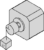
- Inertia load (TJ)
TJ = J * dw/dt
J = M * (R12+R22) / 2 (Kg * cm)
M: mass
R1: outside radius
R2: inside radius
dw/dt: angular acceleration 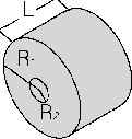
• Speed-Torque Characteristics
The dynamic torque curve is an important aspect of stepping motor’s output performance. The followings are some keyword explanations.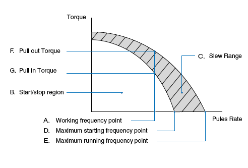 A. Working frequency point express the stepping motors rotational speed versus the drive pulse rate.
n = q * Hz / (360 * D)
n: rev/sec
Hz: the frequency value or the driver pulse rate.
D: the subdividing value of motor driver
q: the step angle of stepping motor E.g.: 1.8° stepping motor, in the condition of I/2 subdividing (each step 0.9°) runs at 500Hz its speed is 1.25r/s. B. Start/Stop region: the region in which a stepping motor can be directly started or stopped. C. Slew Range: the motor cannot be started directly in this area. It must be started in the start/stop region first and then accelerated to this area. In this area, the motor can not be directly stopped, either. Otherwise this will lead to losing-step. The motor must be decelerated back to the start/stop region before it can be stopped. D. Maximum starting frequency point at this point, the stepping motor can reach its maximum starting speed under unloaded condition. E. Maximum running frequency point at this point the stepping motor can reach its maximum running speed under an unloaded condition. F. Pull-in Torque: the maximum dynamic torque value that a stepping motor can load directly at the particular operating frequency point. G. Pull-out Torque: the maximum dynamic torque value that a stepping motor can load at the particular operating frequency point when the motor has been started. Because of the inertia of rotation the Pull- Out Torque is always larger than the Pull-In Torque.
• Calculate the Acceleration Torque
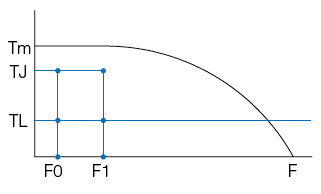
The torque meeded to accelerate the system inertia is often larger than the friction torque of the load. This limits how quickly the load can be accelerated. As shown by the following graph: the dynamic torque performance of a stepping motor is constant at low speeds. But at higher speeds, the torque drops as speed increases. (influenced by the motor inductance and drive voltage)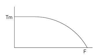 A. Accelerated Motion of Straight Line
Motor's load value is known as TL, it has to be accelerated from F0 to F1 in the shortest time(tr), what is the value of tr?
(1). Generally TJ = 70%Tm
(2). tr = 1.8 * 10 -5 * J * q * (F1-F0)/(TJ-TL)
(3). F (t) = (F1-F0) * t/tr + F0, 0
 B. Exponential Acceleration
(1). Generally
TJ0 = 70%Tm0,
TJ1 = 70%Tm1,
TL = 60%Tm1
(2). tr = F4 * In [(TJ0-TL)/(TJ1-TL)]
(3). F (t) = F2 * [1 – e^(-t/F4)] + F0, 0F2 = (TL-TJ0) * (F1-F0)/(FJ1-TJ0)
F4 = 1.8 * 10-5 * J * q * F2/(TJ0-TL)
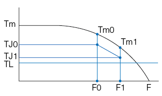 Note: J is the rotational inertia of motor rotor plus the load, q is the angle of each step, it equals the step angle of stepping motor when motor runs in full step.
 • Reduction of Vibration and Noise
In a non-loading condition, stepping motors may appear to have vibration or even lose steps when the motor is running at or close to resonant frequency. Solutions for these conditions include:A. Have the motor operate outside of this speed range.
B. Micro-step is used for increasing a motor’s step resolution. By adopting the micro-step driving method, you can divide one step into multiple steps thereby reducing the vibration. This is accomplished by controlling the motor's phase current ratio. Micro-step does not increase step accuracy. However it will allow a motor to run more smoothly and with less noise. When the motor runs in half step mode the motor torque will be 15% less than running in full step mode. If the motor is controlled by sine wave current the motor torque will be reduced by 30% if using the same peak current.
C. Use 0.9° 2 phase step motor, or a three phase step motor.
