How to control a stepper motor?
Stepper motors can directly receive digital signals. In the past, simpler control circuits relied on digital logic circuits, but these had limited flexibility. Currently, stepper motor control systems offer enhanced functionality, greater system flexibility, and improved reliability, leading to their rapid adoption and widespread application. 
Theoretically, closed-loop control is more reliable than open-loop control. However, closed-loop control systems for stepper motors tend to be more expensive and are susceptible to sustained mechanical oscillation. To achieve superior dynamic performance, it is preferable to choose DC or AC position servo systems instead. Therefore, stepper motors predominantly operate with open-loop control.  Figure C: Serial Control with Microcontroller Pulse allocators are available as dedicated chips on the market, such as the CH250 and L297. The CH250 is specifically designed for three-phase stepper motors, while the L297 is intended for two-phase stepper motors or four-phase stepper motors.
  Figure D: Pure Software Parallel Control 2) Combined Software and Hardware Method The combined software and hardware method reduces the microcontroller's workload and hardware resource consumption compared to the pure software method, as shown in Figure E. In this figure, the P1 port of the 8031 microcontroller is used for signal output, with P1.3 to P1.7 left unconnected. Only P1.0 to P1.2 are connected to the lower three address lines of an EPROM2764, allowing the selection of 8 address units, each corresponding to a specific state. The lower four data output lines of the EPROM2764 serve as control lines for the A, B, C, and D phases of the stepper motor. The hardware is designed so that the windings are energized at low signal levels. In this setup, the EPROM2764 functions as a decoder, simplifying the system design more convenient for the microcontroller to control through predefined input-output relationships.
  Figure E: Combined Software and Hardware Parallel Control
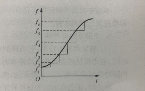
When using a microcontroller to control the acceleration and deceleration of a stepper motor, the key is to regulate the time interval between each phase change. During acceleration, the pulse train density gradually increases, while during deceleration, it decreases. If the microcontroller uses a timer interrupt to control the motor speed, acceleration, and deceleration are essentially achieved by continuously adjusting the timer's load value. For each frequency step, the software can determine the required load value using a table. To simplify programming, it is not necessary to calculate the load value for every step. Instead, a stepped curve can be used to approximate the acceleration/deceleration curve. Figure G illustrates the stepped approximation of an exponential acceleration curve. Since motor deceleration is the inverse of acceleration, the same stepped approximation method is applied to load frequency during deceleration. To achieve accurate step count control for stepper motors, significant software efforts are required. First, to ensure the total step count remains precise, a mechanism must be established to verify whether the specified step count has been reached. This verification should occur every time the motor changes phases. For instance, before the motor starts moving, the specified total step count can be stored in certain memory locations in the RAM. As the motor rotates, the software decrements these values based on the number of phase transitions while simultaneously checking if the stored value has reached zero. If it does, it indicates that the motor has completed the specified number of steps in either the forward or reverse directions, prompting it to stop and enter a locked state. The direction of rotation (forward or reverse) can be determined by the status of a direction flag bit, ensuring precise and controlled movement.

1. Classification of Stepper Motor Control Systems
Digital control systems with stepper motors as the actuating element are categorized into open-loop and closed-loop controls. Open-loop control, as depicted in Figure A, open-loop control does not incorporate position feedback and does not require position sensors like optical encoders, making the control system relatively inexpensive. To ensure accurate positioning, a sufficient margin must be designed into the system. This means the drive pulse frequency of the stepper motor cannot be set too high, and the mechanical load on the motor cannot be too heavy. If a short-term overload causes the stepper motor to lose steps, positioning errors will occur. As shown in Figure B, closed-loop control employs position sensors such as optical encoders to provide feedback on the actual position of the motor to the computer. If the stepper motor loses steps, the computer detects that the actual position of the motor does not match the set value and compensates by sending additional pulses until the actual position of the motor aligns or closely approaches the set value. |  |
| Figure A: Open-loop control | Figure B: Closed-loop control |
2. Microcontroller Control of Stepper Motors
Microcontrollers are commonly used as control chips for stepper motors. When controlling a stepper motor with a microcontroller, whether in an open-loop or closed-loop system, the control methods can be categorized into serial control and parallel control.2.1. Serial Control
Figure C illustrates the schematic diagram of driving a stepper motor through serial control using an 8031 microcontroller. There are only two control lines between the microcontroller and the power interface of the stepper motor: one for transmitting a step pulse train (CP) and the other for sending a level signal to control the rotation direction. The power interface circuit for serial control contains a pulse allocator (also known as a ring allocator). Which converts a single-channel pulse into cyclically varying multi-phase pulses. It has a single input and multiple outputs. As pulses are input sequentially, the output voltages of the various channels alternate between high and low. For example, a three-phase pulse allocator has three output channels: A, B, and C. In a single three-phase operation mode, when the microcontroller sends pulses to the pulse allocator, the output voltages of the three channels alternate in the sequence A→B→C→A→..., supplying power to the three-phase windings of the stepper motor through power amplifiers. This sequential voltage change causes the stepper motor to rotate step by step. The pulse allocator typically also features a rotation direction control terminal. Depending on whether the signal at this terminal is low or high, the sequence of alternating output voltages follows either A→B→C→A→... or A→C→B→A→..., thereby determining whether the stepper motor rotates in the forward or reverse direction. Figure C: Serial Control with Microcontroller Pulse allocators are available as dedicated chips on the market, such as the CH250 and L297. The CH250 is specifically designed for three-phase stepper motors, while the L297 is intended for two-phase stepper motors or four-phase stepper motors.
 2.2. Parallel Control
In parallel control, the microcontroller directly generates multi-phase pulse wave signals through multiple parallel port lines. These signals are then amplified in power and delivered to the respective phase windings of the stepper motor. This approach eliminates the need for a pulse allocator, as its function can be implemented purely through software or a combination of software and hardware. 1) Pure Software Method In this method, the function of the pulse allocator is entirely executed by software. The software sequentially cycles through and outputs each state required to drive the stepper motor, as illustrated in Figure D. The key advantage of replacing the pulse allocator with a pure software approach is its flexibility, enabling multiple motion control modes. However, this method consumes more computation time and hardware resources of the microcontroller. Figure D: Pure Software Parallel Control 2) Combined Software and Hardware Method The combined software and hardware method reduces the microcontroller's workload and hardware resource consumption compared to the pure software method, as shown in Figure E. In this figure, the P1 port of the 8031 microcontroller is used for signal output, with P1.3 to P1.7 left unconnected. Only P1.0 to P1.2 are connected to the lower three address lines of an EPROM2764, allowing the selection of 8 address units, each corresponding to a specific state. The lower four data output lines of the EPROM2764 serve as control lines for the A, B, C, and D phases of the stepper motor. The hardware is designed so that the windings are energized at low signal levels. In this setup, the EPROM2764 functions as a decoder, simplifying the system design more convenient for the microcontroller to control through predefined input-output relationships.
  Figure E: Combined Software and Hardware Parallel Control
 2.3. Stepper Motor Speed Control
Controlling the speed of a stepper motor essentially involves adjusting the duration of each energized state. There are two methods: software delay and timer delay. 1) Software Delay Method In this method, a delay subroutine is called after each transition of the energized state (phase change). Once the delay ends, the phase change subroutine is executed again. This process is repeated continuously, allowing the stepper motor to rotate at a predetermined speed. 2) Timer Delay Method Microcontrollers typically include several onboard timers/counters. One of these timers can be used by loading an appropriate timer value. After a predetermined period, the timer overflows, generating an interrupt signal that temporarily halts the execution of the main program and switching to the timer interrupt service routine, thereby creating a hardware delay effect. If the stepper motor phase change subroutine is placed within the timer interrupt service routine, the motor will change phases each time the timer interrupts. This approach effectively controls the motor's speed by regulating the timing of phase transitions.3. Acceleration and Deceleration Positioning Control
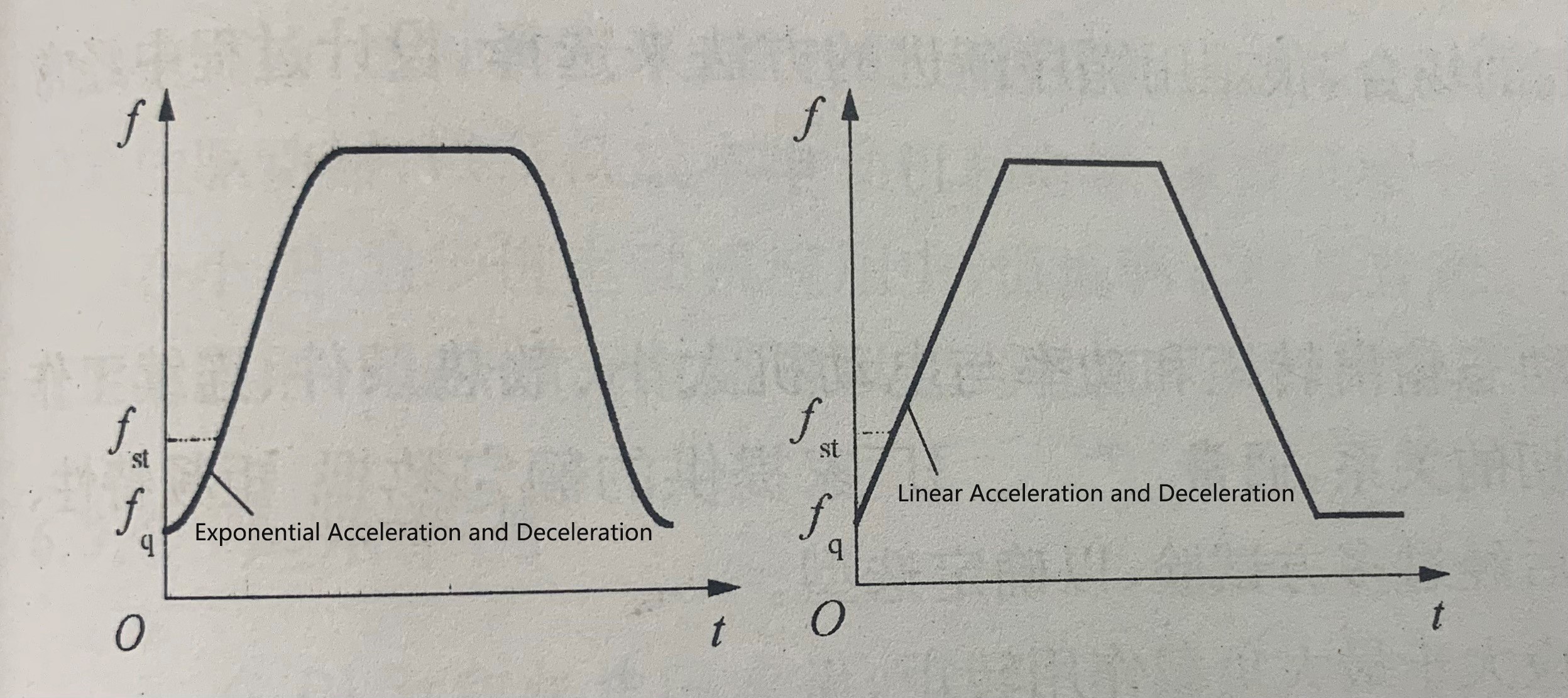
The maximum starting frequency (jump frequency) of a stepper motor typically ranges from a few hundred to several thousand hertz. If the motor is started directly at a frequency exceeding its maximum starting frequency, it will experience a "loss of synchronization" (out-of-step conditions) and, in some cases, may fail to rotate entirely. However, by starting at a frequency lower than the maximum starting frequency and gradually increasing it, the motor can accelerate smoothly and reach its maximum operating frequency. Additionally, when a stepper motor is rotating at high speed, immediately stopping the pulse at the destination to achieve precise positioning is challenging. Due to inertia, the motor often overshoots its target, resulting in out-of-step conditions. If the operating frequency of the motor remains below the maximum starting frequency, out-of-step issues can be avoided. However, this limits the motor's potential, leading to suboptimal performance and low operating speeds. When the loading mechanism rapidly moves from one position to a specified target position, the stepper motor must transition from one locked position, take a series of steps, reach the target as quickly as possible, and lock it into place. This imposes two fundamental requirements on the system: first, the total number of steps must match the given value. Second, the total step time should be minimized. To meet these two requirements, the stepper motor requires acceleration and deceleration positioning control. This means that the stepper motor drives the given load through a sequence of acceleration - constant high speed - deceleration - constant low speed - locking, achieving accurate positioning quickly and stably. There are generally two options for acceleration and deceleration profiles, as shown in Figure F: one follows an exponential law, where acceleration is initially high during the acceleration phase and gradually decreases as speed increases. During deceleration, the deceleration rate is smaller at higher speeds and larger at lower speeds. This profile aligns well with the characteristic of stepper motors, where output torque decreases as speed increases. However, it involves complex calculations. |  |
| Figure F: Acceleration and Deceleration Profiles of Stepper Motors | Figure G: Staircase Approximation of Loading Frequency |
