Power Factor Correction Basics
1.1 What is Power Factor?
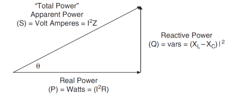
Power factor (pf) is defined as the ratio of the real power (P) to apparent power (S), or the cosine (for pure sine wave for both current and voltage) that represents the phase angle between the current and voltage waveforms (see Figure 1). The power factor can vary between 0 and 1, and can be either inductive (lagging, pointing up) or capacitive (leading, pointing down). In order to reduce an inductive lag, capacitors are added until pf equals 1. When the current and voltage waveforms are in phase, the power factor is 1 (cos (0°) = 1). The whole purpose of making the power factor equal to one is to make the circuit look purely resistive (apparent power equal to real power). Real power (watts) produces real work; this is the energy transfer component (example electricity-to-motor rpm). Reactive power is the power required to produce the magnetic fields (lost power) to enable the real work to be done, where apparent power is considered the total power that the power company supplies, as shown in Figure 1. This total power is the power supplied through the power mains to produce the required amount of real power. The previously-stated definition of power factor related to phase angle is valid when considering ideal sinusoidal waveforms for both current and voltage; however, most power supplies draw a non-sinusoidal current. When the current is not sinusoidal and the voltage is sinusoidal, the power factor consists of two factors: 1) the displacement factor related to phase angle and 2) the distortion factor related to wave shape. Equation 1 represents the relationship of the displacement and distortion factor as it pertains to power factor.
1.2 Understanding Recent Regulations
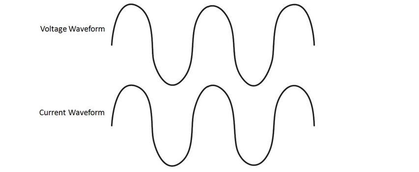
In 2001, the European Union put EN61000-3-2, into effect to establish limits on the harmonics of the ac input current up to the 40th harmonic. Before EN61000-3-2 came into effect, there was an amendment to it passed in October 2000 that stated the only devices required to pass the rigorous Class D (Figure 2) emission limits are personal computers, personal computer monitors, and television receivers. Other devices were only required to pass the relaxed Class A (Figure 3) emission limits. Figure 2. Both Current and Voltage Waveforms are in Phase with a PF=1(Class D)
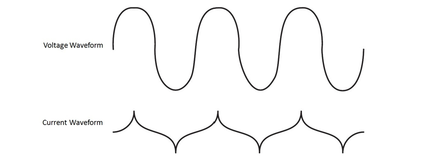
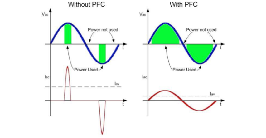
  Figure 3. This is What is Called Quasi-PFC Input with a PF=0.9(Class A) As it says above, it is necessary to align the phase angle of incoming current so that it is in phase with the line voltage. The basic concept is to make the input look like a pure resistor which current waveform follows with voltage waveform as shown in Figure 4. Resistors have a power factor of 1 (unity). This is mainly to meet new regulations aimed at restricting the harmonic content of the load current drawn from power lines. Both users and power companies benefit from PFC, as does the environment. MOONS’ LED driver integrated with active PFC module making your lighting system run better than expectations.
  Figure 4. PFC introduction Note: The home station partial articles originate from the network