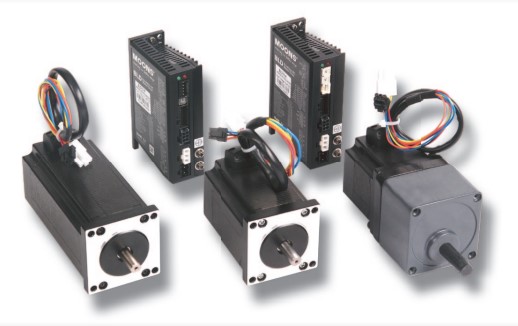
Servo Motor Working Principle
Definition of servo motor
The servo motor, also known as an actuator motor, functions to convert input voltage signals into angular displacement or angular velocity output of the rotating shaft. This input voltage signal is also referred to as the control signal. The primary characteristics of a servo motor include the absence of self-rotation when the signal voltage is zero and a uniform decrease in speed as torque increases.
Servo Motor Working Principle
The servo motor is a typical closed-loop feedback system. Its terminal (output end) drives a linear proportional potentiometer for position detection. This potentiometer converts the angular coordinates into a proportional voltage and feeds it back to the control circuit board. The control circuit board compares this feedback with the input control pulse signal, generates a correction pulse, and drives the motor to rotate either forward or backward. This process ensures that the output position of the shaft matches the desired value, causing the correction pulse to approach zero, thereby achieving precise positioning of the servo motor. The rotor inside the servo motor is a permanent magnet. The U/V/W three-phase electrical current, controlled by the driver, generates an electromagnetic field that causes the rotor to rotate. Simultaneously, the motor's built-in encoder sends feedback signals to the driver. The driver compares these feedback signals with the target values and adjusts the rotor's angle of rotation accordingly. The accuracy of the servo motor depends on the precision of the encoder, which is determined by the number of lines.Classification of servo motors
According to the nature of the power supply, servo motors can be divided into DC servo motors and AC servo motors. AC servo motors are usually two-phase and their rotors use either cage rotors or hollow cup rotors. The output power of two-phase servo motors typically ranges from 0.1 to 7.5 kW, with the commonly used ones being below 750 W. The structure and principles of DC servo motors are similar to those of ordinary DC motors. By changing the control voltage, the speed and direction of the servo motor can be adjusted. The output power of DC servo motors typically ranges from 1 to 750 W.AC servo motor
The structure of the AC servo motor stator is essentially similar to that of a capacitor-phase split-phase asynchronous motor. The stator is equipped with two windings positioned 90° apart. One is the excitation winding Rf, which is always connected to the AC voltage Uf; the other is the control winding L, which is connected to the control signal voltage Uc. Therefore, the AC servo motor is also known as a two-phase servo motor. The rotor of an AC servo motor is typically made in a squirrel cage type. However, to ensure the servo motor has a wide speed regulation range, linear mechanical characteristics, no "self-rotation" phenomenon, and fast response performance, it needs to have two key features compared to ordinary motors: high rotor resistance and low rotational inertia. Currently, there are two widely used rotor structures: one is a squirrel cage rotor with bars made of conductive materials with high resistivity, designed to be slender to reduce rotational inertia. The other is a hollow cup rotor made of aluminum alloy, with a very thin wall, only 0.2-0.3mm thick. To reduce the magnetic resistance of the magnetic circuit, a fixed inner stator is placed inside the hollow cup rotor. The hollow cup rotor has low rotational inertia, quick response, and smooth operation, making it widely adopted. When there is no control voltage in the AC servo motor, the stator only produces a pulsating magnetic field generated by the excitation winding, and the rotor remains stationary. When a control voltage is applied, a rotating magnetic field is created in the stator, causing the rotor to rotate in the direction of the rotating magnetic field. Under a constant load, the motor speed varies with the control voltage magnitude. If the phase of the control voltage is reversed, the servo motor will reverse its direction. The output power of the AC servo motor generally ranges from 0.1 to 100W. When the power frequency is 50Hz, the voltage options are 36V, 110V, 220V, and 380V. When the power frequency is 400Hz, the available voltages include 20V, 26V, 36V, and 115V, among others.Application of servo motor
In recent years, the application scope of servo motors has been expanding, and the requirements for them have been continuously increasing. This has led to the emergence of many servo motors utilizing new materials, technologies, and structures. Examples include low-inertia DC servo motors with hollow cup armatures, disc armatures, and slotless armatures; brushless DC motors that use position sensors and electronic switch circuits to replace armatures and commutators; and permanent magnet, reluctance, and hysteresis synchronous servo motors. There are many types of servo motors and they are widely used. The basic requirements of the automatic control system for servo motors can be summarized as follows:1) Wide speed regulation range. The speed of the servo motor must be continuously adjusted within a wide range.
2) The mechanical characteristics and adjustment characteristics are linear. Linear mechanical characteristics and adjustment characteristics help improve the dynamic accuracy and stability of the automatic control system.
3) No "Self-rotation" phenomenon: When the control signal is eliminated, the servo motor should stop immediately, that is, the servo motor should not have the "self-rotation" phenomenon.
4) Small control power, small size, light weight, and large starting torque.
5) Small electromechanical time constant and low starting voltage. When the control signal changes, the response should be fast and sensitive.
