What is a Permanent Magnet Stepper Motor?
A permanent magnet stepper motor, also known as a PM stepper motor, is an electric motor that utilizes the magnetic field generated by the direction of the coil current to repel or attract the rotor's magnetic field, enabling the motor to rotate forward or in reverse. 
 The stepper motor driver responds to external control pulses and direction signals through its internal logic circuitry. For each control pulse and direction signal received, the driver powers the motor windings to move the rotor one step forward, in reverse, or hold it in position. For example, in a 7.5 degree two phase step motor: When both phases are energized with DC current, the motor will stop rotating and hold in position. The maximum torque the motor can maintain with rated DC current is known as the rated holding torque. Reversing the current in one phase causes the motor to move one step (7.5 degrees) in a specific direction. Reversing the current in the other phase would move the motor one step (7.5 degrees) in the opposite direction. As the current alternates sequentially between phases, the motor continues stepping in the desired direction with high precision. For a 7.5-degree step motor, there are exactly 48 steps in one full revolution. Two phase stepping motors are available with two types of windings: bipolar or unipolar. In a bipolar motor, each phase has a single winding, and the motor steps as the current in each winding is reversed, requiring a drive with eight electronic switches. In a unipolar motor, each phase has two windings connected in opposite directions, and the phase current is reversed by activating alternate windings within the same phase. This setup requires only four electronic switches. Bipolar operation generally provides about 40% more holding torque than unipolar operation, as 100% of the winding is energized in the bipolar configuration. The dynamic torque curve is a key factor in assessing the stepping motor's performance. The following are some keyword explanations.
  A. Working frequency point: represents the relationship between the stepping motor's rotational speed and the drive pulse rate. n = q * Hz / (360 * D)
n: rev/sec, Hz: the frequency value or the driver pulse rate, D: the subdividing value of the motor driver, q: the step angle of the stepping motor B. Start/Stop region: the range within which a stepping motor can be directly started or stopped. C. Slew Range: In this range, the motor cannot be started directly; it must first be started in the start/stop region and then accelerated into the slew range. Similarly, the motor cannot be stopped directly in this range, as doing so may cause step loss. To stop, the motor must be decelerated back to the start/stop region. D. Maximum starting frequency point: The point at which the stepping motor can achieve its maximum starting speed under unloaded conditions. E. Maximum running frequency point: The point at which the stepping motor can achieve its maximum running speed under unloaded conditions. F. Pull-in Torque: The maximum dynamic torque a stepping motor can handle directly at the specific operating frequency point. G. Pull-out Torque: The maximum dynamic torque value a stepping motor can handle at the specific operating frequency point once the motor is already in motion. Due to rotational inertia, the Pull-Out Torque is always larger than the Pull-In Torque.
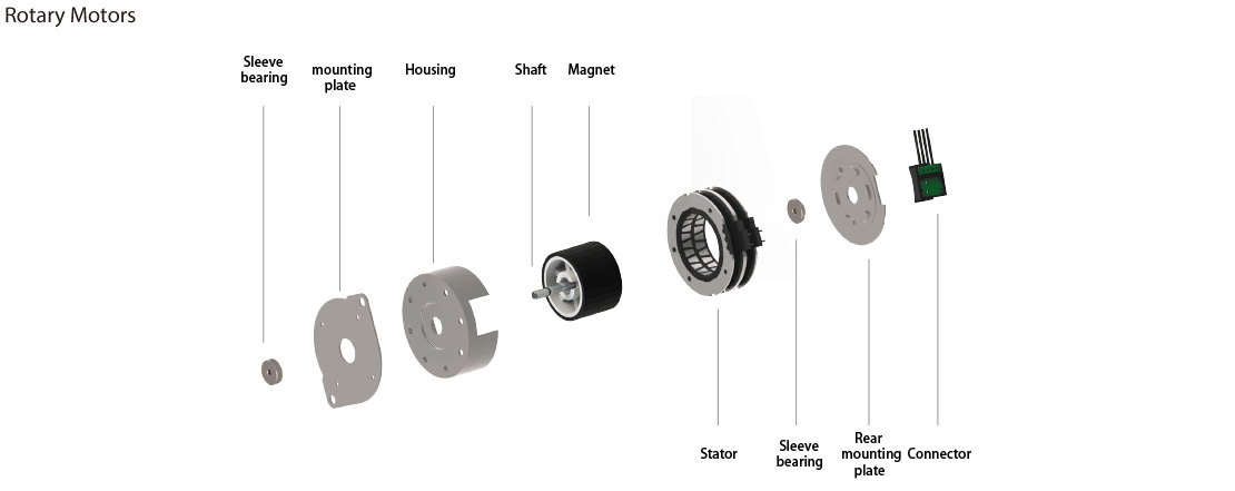
Permanent Magnet Stepper Motor Structure

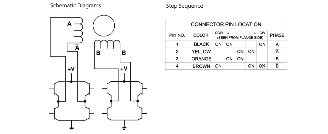
Permanent Magnet Stepper Motor Operating Principles
 The stepper motor driver responds to external control pulses and direction signals through its internal logic circuitry. For each control pulse and direction signal received, the driver powers the motor windings to move the rotor one step forward, in reverse, or hold it in position. For example, in a 7.5 degree two phase step motor: When both phases are energized with DC current, the motor will stop rotating and hold in position. The maximum torque the motor can maintain with rated DC current is known as the rated holding torque. Reversing the current in one phase causes the motor to move one step (7.5 degrees) in a specific direction. Reversing the current in the other phase would move the motor one step (7.5 degrees) in the opposite direction. As the current alternates sequentially between phases, the motor continues stepping in the desired direction with high precision. For a 7.5-degree step motor, there are exactly 48 steps in one full revolution. Two phase stepping motors are available with two types of windings: bipolar or unipolar. In a bipolar motor, each phase has a single winding, and the motor steps as the current in each winding is reversed, requiring a drive with eight electronic switches. In a unipolar motor, each phase has two windings connected in opposite directions, and the phase current is reversed by activating alternate windings within the same phase. This setup requires only four electronic switches. Bipolar operation generally provides about 40% more holding torque than unipolar operation, as 100% of the winding is energized in the bipolar configuration. The dynamic torque curve is a key factor in assessing the stepping motor's performance. The following are some keyword explanations.
  A. Working frequency point: represents the relationship between the stepping motor's rotational speed and the drive pulse rate. n = q * Hz / (360 * D)
n: rev/sec, Hz: the frequency value or the driver pulse rate, D: the subdividing value of the motor driver, q: the step angle of the stepping motor B. Start/Stop region: the range within which a stepping motor can be directly started or stopped. C. Slew Range: In this range, the motor cannot be started directly; it must first be started in the start/stop region and then accelerated into the slew range. Similarly, the motor cannot be stopped directly in this range, as doing so may cause step loss. To stop, the motor must be decelerated back to the start/stop region. D. Maximum starting frequency point: The point at which the stepping motor can achieve its maximum starting speed under unloaded conditions. E. Maximum running frequency point: The point at which the stepping motor can achieve its maximum running speed under unloaded conditions. F. Pull-in Torque: The maximum dynamic torque a stepping motor can handle directly at the specific operating frequency point. G. Pull-out Torque: The maximum dynamic torque value a stepping motor can handle at the specific operating frequency point once the motor is already in motion. Due to rotational inertia, the Pull-Out Torque is always larger than the Pull-In Torque.
